The first idea I had for this project came to me very quickly. Originally, I wanted to get a piece of wood, put two toy soldiers on opposite ends and use DC and Servo motors to have them pass something from the right side to the left. Knowing that would be very difficult in a short span of time, I simplified my idea. I would keep the object going from right to left but make it look like it’s orbiting! Maybe I could make a few planets pop out from the wood and orbit around one another? Nah, still too complex to do in less than a week. The idea of things popping out a bit really stuck with me though, it reminded me of old storybooks, which got me thinking about comic books. I used to be a big Batman nerd and the frame of the Joker laughing from “The Killing Joke” always stuck out in my mind so I figured why not try to do that.
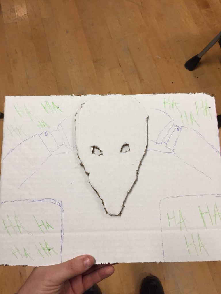
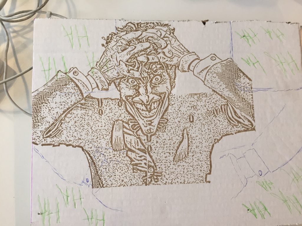
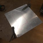
I started by creating a model out of cardboard. I designed the background in illustrator and photoshop. Once I was happy with the background, I hand traced the Joker’s body onto the cardboard. This was just so I could get a reference of how much mat I needed to buy and how big I wanted my canvas to be. After the initial canvas was set I cut out a rough sketch of the Joker’s head on cardboard. I wanted the background to be the famous image but I wanted the project to have some depth hence making a different, slightly larger head. I knew I could take this head and put it on something – likely wood – that would have my motor enclosed in it.
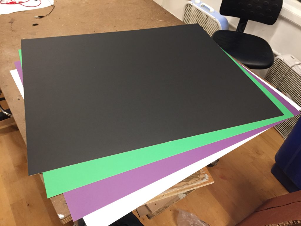
Happy with the dimensions of all my things I made my Joker image on Photoshop/Illustrator which took quite a bit of time. Before I etched that on anything though I needed to decide what I was going to be etching on. I know I wanted to use mat board but how much and what color? I decided to have a green background covered up by a black mat board with the words HA cut out from it repeatedly. I figured this would give me depth and make the HA’s pop a bit more. I knew I had to incorporate the Joker Purple into the project too and that I would either want his face or his gloves to be white. So I went out and bought a bunch of green, purple, white and black mat from Blick.
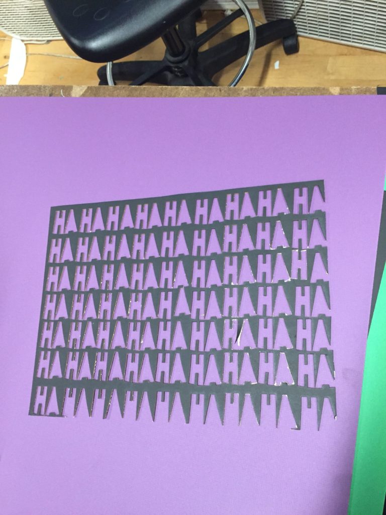
I took my black mat and cut out the HA’s and it came out…ok. I was dumb and didn’t realize that the tiny part of the A’s would fall out because they wouldn’t be attached to anything. Also, because there were so many HA’s spread out over such a large canvas, some cut out very easily where as others were a bit more stubborn. With the HA’s cut out, rather then cut again I thought it would be cool to write in the section that was missing from the A’s myself. I thought by having a more human element, the HA’s would convey a tone closer to that of the Joker’s than a clean and neat one.
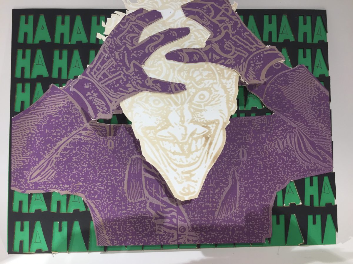
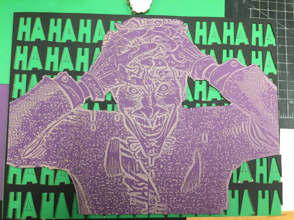
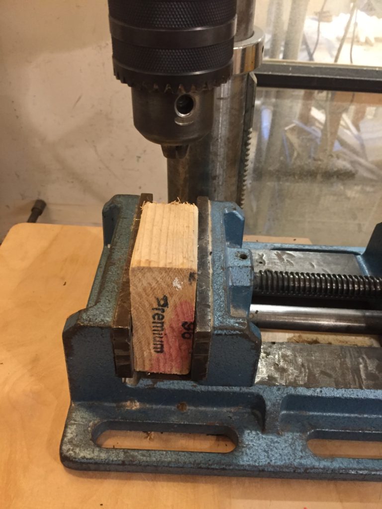
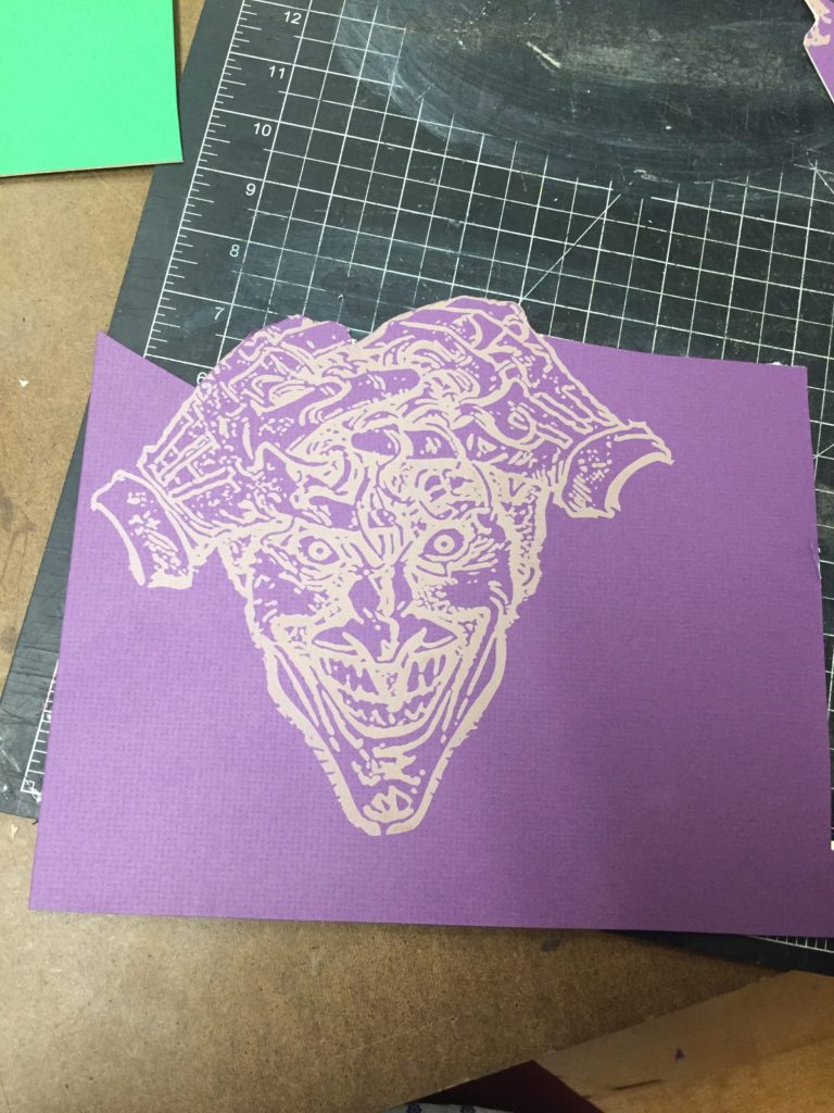
With the background done, I etched the Joker’s body and face for the background. Instead of using the laser to cut this though, I cut it out by hand with a box cutter, which went through the mat really easily and saved me a lot of time; it would’ve taken forever to cut out the joker the way I wanted I think. With the background fully done, all I needed to do now was find something that would let me attach a servo to it and elevate the Joker’s head and make the actual Joker head. I found perfect wood block in the shop and bore a 1” hole into it with the drill press (I measured the servo before hand to make sure the size was correct). I then bore a 0.5” hole into the side so that I could run my wire through it. Originally I was going to drill my servo into the block of wood but there was no need as the servo fit snuggly into the hole.
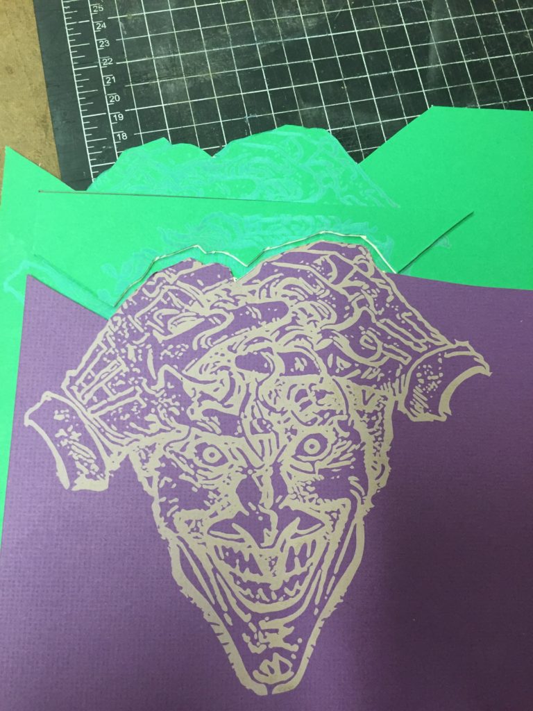
I measured out a proper size for the Joker’s head and etched it in purple and green mat. I wanted to cut out the hair from the green mat and cut out the space where it would go in the purple but when I tried to do it by hand it was super sloppy and didn’t look too great. By this point in the project, I hadn’t used the white mat at all and I was curious to see what the etch would look like on it. What came out was sort of glossy and had a nice…sheen to it I guess you could say. I figured I could take the purple gloves from the purple mat, cut them out and glue them to the white head to continue to add depth and when I tried it I was really pleased with the result.
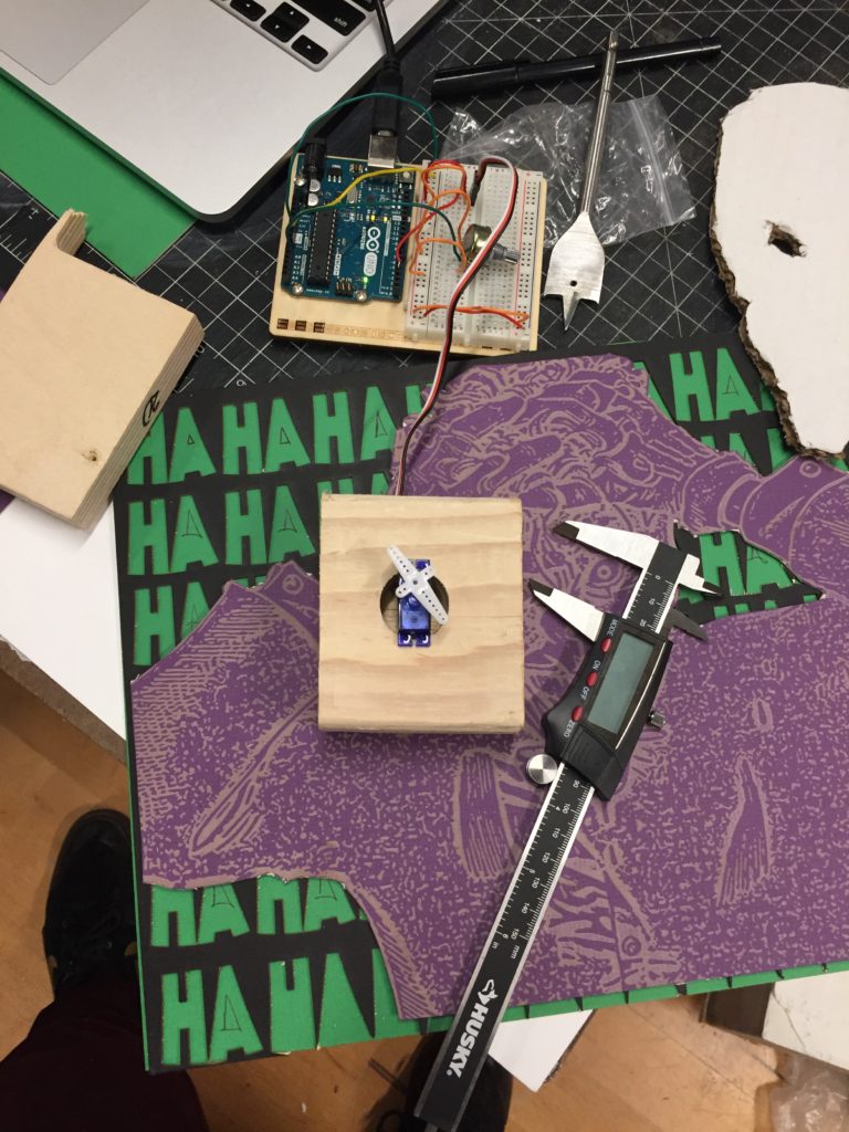
With all the different components now made, all that remained was figuring out positioning for the wood block. I glued one of the plastic detachable servo motor pieces to the point on the Joker’s head that I wanted it to pivot from and attached it to the servo. I moved the block to a place where I was happy with and glued it with wood glue to that spot. There was so much surface area to cover with glue so I knew that the slightly heavy block wouldn’t be going anywhere.
Once the glue was set, I programmed the servo and gave it a test run and it turned out really well!
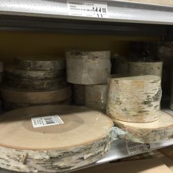
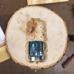
Man, what a journey this assignment was! Originally, I was going to do a small enclosure for a book but I realized I wanted more of a challenge; I wanted to make a Gameboy. My inspiration came when Ben was showing us hollowed out blocks of wood with pencil markings that – to me – resembled the controls of a Gameboy. Knowing that I would need a piece of wood that had a lot of depth so it could be hollowed out, I went out looking. Lowes had nothing thicker than an inch, and Home Depot wasn’t helpful either. Enter Michaels. They had a SECTION of tree stumps including the one I purchased. At the time, I wasn’t quite sure what I was going to do with the slab of wood, I was just happy that it was thick and that it had some character to it (I also made sure it could be used for etching should I decide to go that route).
Friday morning I brought my old Gameboy Color to school and took it apart. As I sat there with it’s components in my hand, I realized it would be sort of lame and unoriginal to just take those components and place them in a new enclosure. It lacked creativity and didn’t excite me as much. I thought it would be cooler to incorporate some P-Comp into the work by making a game on my Arduino and placing that in an enclosure. Before I could begin any of that enclosure work however, I would need to know the size and height of the game. Would there be a lot of wires? Would it be compact and malleable or huge and begrudging? I found a link on Instructables to a Tetris game made on the Arduino.
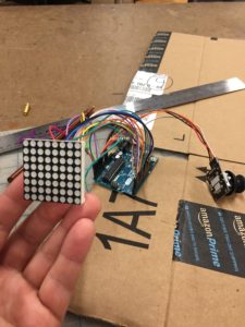
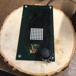
After two trips to Tinkersphere (best to make sure you have the correct parts on the first trip rather than walk back in the rain to exchange the wrong components), I set to wiring and programming the microcontroller. After everything was wired up, I provided power to the microcontroller only to realize something was wrong. About six hours later, and with some help from resident Joe Mango, I realized that the 8×8 LED matrix I purchased was a slightly different model than the one featured despite them looking the identical. It turns out that the anodes and cathodes in an 1088 8×8 LED matrix differ from those in the 1588 8×8 LED Matrix and as a result the code provided on instructables would not work unless adjusted. Once the code was properly corrected I had my working Tetris and all I needed was a proper enclosure.
Originally, I wanted to cut out a Gameboy-like box to put Tetris in but a few factors led to me changing my mind: I knew I would not be able to laser cut the tree slab, I knew it would be difficult to cut it with any precision due to its circularity, I wanted to maintain the aesthetic the tree provided. I decided maybe it would be less complex and more efficient to maintain the slabs form and just hollow it out as opposed to trying to make it hand held.
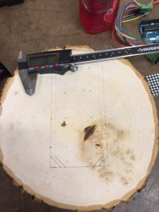
I measured Tetris – the arduino, the LED matrix, the joystick and the height of the wires – and figured out how deep I needed to drill into the wood.
I used a 1.5 inch bit and did a bunch of passes with that, then used a 0.5 inch bit to clean it up and make it flat.
Now, the biggest difficulty I faced was how deep could I drill into the wood without boring through to the bottom. I was left with a choice: bore straight through and put a slab of acrylic on the bottom that could be screwed in an out and loaded into the wood like a little elevator, or keep the floor all wood and load everything through the top. I decided to go with the later. As a result, I needed to know how deep I could go before hitting the bottom. I measured the height of the wood, subtracted about 1/3th of an inch and drew a line in dry erase marker on the bit. Though I couldn’t see that line when the bit was spinning, when I stopped drilling I could see approximately how much deeper I needed to go. The issue was I didn’t trust myself. I drilled 9 holes about an inch away from the marked line and then had to do it all over again when I wasn’t satisfied. Had I trusted my measurements, that process could’ve taken an hour as opposed to the two it took.
I am text block. Click edit button to change this text. Lorem ipsum dolor sit amet, consectetur adipiscing elit. Ut elit tellus, luctus nec ullamcorper mattis, pulvinar dapibus leo.
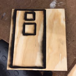
With my bedding all set, I set out to create a top to screw on to enclose the microcontroller. My original idea was to laser cut a piece of quarter inch ply into the piece to be screwed on and on that piece would be cut out a box to stick the LED and a box to put the joystick. After making the file in illustrator, I enlisted the help of Jesse to give me a refresher course on laser cutting. The first go wasn’t great, it was catching flame – very briefly mind you – a bit too frequently. After the fourth or fifth go there was no change, the wood just looked a LOT darker and it wasn’t going through. At this time, I had to go help out a group with a sound and video project. When I returned, I cut out another piece of ply (from the same ply that was used before which is important for later) and was comparing it to the burnt piece.
John saw me looking at the burnt piece and asked me what happened. I told him and he figured it was because the auto-focus wasn’t turned on the laser cuter. We set up everything again with this new piece of ply and while it wasn’t catching fire as much, after five passes it wasn’t cutting through. John told me it probably wasn’t going to cut if it hadn’t done so after all these passes and asked if he could cut the wood open to see what was happening. I obliged.
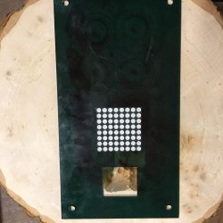
While he was operating on the ply, I pivoted to using the acrylic that I had left. I thought it would be cool aesthetically to mix something a little more technical and glossy looking with something natural like wood. Before I laser cut the same design, I remembered the mistake I made with my keychain last time: I needed to laser cut holes to drill into because drilling into acrylic can be a bit risky. I adjusted the file accordingly and my first cut came out looking really good. John returned and showed me that the wood had stopped cutting about 2/3rds of the way through and that it was just an issue with the wood: “ply is a tricky variable.”
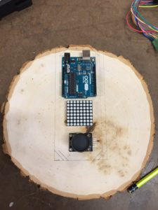
Now that I had the top of the design, I needed to make sure that it would be able to be drilled on properly with all the electrical components fitting inside. I set up Tetris and tried to shove all the wires in but to no avail, the bed would have to be lowered by at least another half inch if not another full inch. I returned to the drill press and drilled deeper. Turns out I used the same bit I drilled with on Saturday and had forgotten to remove my dry erase line. What do you know, when the bed was at the proper height, it matched the original marking I made on Saturday. Had I just trusted my measurement, I wouldn’t have had to use the drill press for a third time.
With the bed correct, I was able to place the microcontroller into the wood snuggly. I drilled a hole in the top so that I could provide power to the board, wired everything together and it all seemed to work… minus one thing: the joystick had nothing to lock it into place.
Due to the bizarre measurements of the joystick – it juts out at weird places and needs to almost be fully exposed to have a full range of motion – I couldn’t just lock it into the laser cut like the 8×8 LED did. At first I thought maybe I could cut out some acrylic, bend it with the acrylic bender, glue it to the inside of the enclosure and provide a little bed for the joystick to rest upon. After tinkering with measurements and cardboard for a while, I came up with a mini-prototype. Then I realized, on the left side of the joystick there are 5 electronic pins to run wires to, if I was going to do this with acrylic I would have to properly measure the minute little bends, and laser like 1/16th holes in the acrylic to run the wires through and even then it may not work because of the lack of malleability of the wire heads. (As I write this however I realize that rather than resting the joystick in the bed, I could’ve done the same thing but turned the acrylic upside down and had it sit upon it…though I think what I figured out is a similar solution).Rather then do that, I thought maybe I could rest the joystick on a small piece of wood inside the enclosure and use that to lock it in place. I found a piece of scrap, cut it to be about an inch by an inch with the band saw and rested it in the enclosure and it worked perfectly.
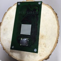
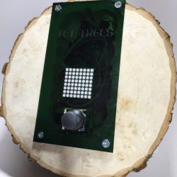
I still wasn’t satisfied though. The acrylic was looking a bit bland and needed something a bit clever to pull it all together. I had tetris, I had a tree, I had Tet-Trees. I etched that into the acrylic and there it was, a final project that I am really, really proud of. Would I change a few things? Absolutely. I’d use a different acrylic so the etching would pop a lot more and I’d figure out a better way to lock that joystick in place but still, I think it’s a really cool piece and I’m excited to show it off.
We’ve talked about in class how the purpose of some of these assignments is to be able to construct something in a short period of time. I sort of took that to the extreme this week. Usually, I buy my materials on Friday, start working on Saturday and try to be finished on Monday however my dad came into town on Friday and I wasn’t able to get any work done on the weekend giving myself a really short amount of time. I interpreted that as a new challenge.
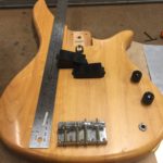
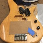
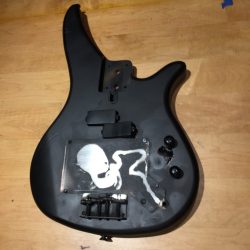
Rather than find two completely new separate materials, I decided to take advantage of an old broken bass I had laying around. I looked up the model and confirmed that it was indeed made out of Maple, making it eligible to be used.
I am text block. Click edit button to change this text. Lorem ipsum dolor sit amet, consectetur adipiscing elit. Ut elit tellus, luctus nec ullamcorper mattis, pulvinar dapibus leo.
Originally, I wanted to take some delrin, etch a design into it and fasten it to the empty space in the bass between the pickups and the bridge.
However, it would take a day or two for the delrin to get to me and I wanted to start immediately. Than I thought maybe I could use leather and it didn’t seem to appealing to me so I pivoted to aluminum. I found a shop in the city that sold it – Metalliferous – gave them a call to confirm they had sheets and head up town.
When I got there I found two sheets of aluminum and asked them if it was anodized to which they said they didn’t know but they were pretty sure it was. I asked if it could be laser etched then – knowing it needed to be anodized to be etched therefore if they knew it could etched with a laser it would be anodized – to which they said, “absolutely”.
Cut to an hour later, I decide to double check with John who shows me that it is indeed NOT anodized. I had two options: change my approach or go up and return the aluminum. I decided to go with the former. I figured I could just cut out my piece and than spray paint a stencil onto it.
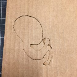
I measured the area I wanted the aluminum to cover and used those measurements to make a cardboard prototype. Once I was happy with that I used those same measurements and looked for some nibblers to cut my aluminum. Jordan saw what I was about to do and introduced me to the power nibbler, which made that process a hell of a lot easier. After cutting out my aluminum, I focused on creating the design to put on top of it. A few nights prior, I had seen one of my favorite bands, Sigur Ros, live and was feeling really inspired by them. One of their album covers is a fetus and I thought it would be cool to put that in what looks like the womb of the bass. I took the album cover and put it into photoshop and, with much help, vectorized it and prepared it to be cut. I used some excess cardboard as material and cut out a little fetus I was happy with.
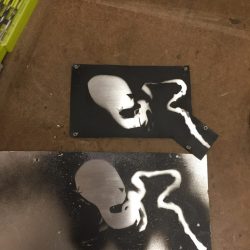
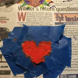
Knowing I didn’t have a lot of excess materials, I wanted to make sure I was going to get things right. I decided to take my fetus etch and spray paint it over some excess aluminum. I prepped the aluminum by washing it off and scraping it with a scouring pad, applied duct tape to the bottom of the fetus and placed it on the aluminum. My first spray was really successful so I moved on to doing the same procedure on the sized cut of aluminum. This one wasn’t so successful. I applied too many coats and it bled through the bottom of the cardboard and it looked awful. Luckily, the prototype spray looked good, so I just cut that out to the right proportions and screwed it on the bass.
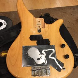
I was unhappy with how the aluminum looked with the maple wood backing though so I decided to take the spray I had remaining and cover the entire bass black so the fetus would pop more. I think it ended up looking really cool. For the future, I’d love to make it so that when the bass is plugged in, the fetus lights up –hence why the umbilical chord goes to the plug-in jack – but that’s a project for a different day.
So after my big project last week, I decided I didn’t want to bite off more than I could chew. As it happened, when we were receiving the assignment I was wearing a – rather nerdy – Zelda t-shirt.
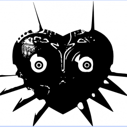
I always thought the masks were aesthetically appealing and I thought the laser cutter would be a great way to try to make one so I decided to use some free acrylic I got – thanks to the ITP Listserv – to make Majora’s Mask key-chain’s.
I started by finding an image of the mask that was high quality
However, when I tried to use the “Trace Image” feature on Illustrator, the image that showed up wasn’t going to work for the laser cutter.
I asked a close friend of mine why this was happening and she told me that Illustrator wasn’t too good at live tracing color images. Not really know Illustrator at all I was a bit lost, so I attended Friday’s workshop on laser cutting. Rebecca let me know that rather than use Illustrator straight away, it would be best to upload the image to Photoshop and dull down all the colors to black.
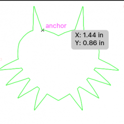
I sent the new image back over to Illustrator, zoomed in to fix small discrepancies and saved the document using the ITP template in order to prepare it for laser cutting.
With the supervision of Aaron, I pulled up my image, set the preferences properly and began to cut my first mask. The first cut came out really well but it was going to be way too big for a keychain.
I reduced the size of the template, adjusted my acrylic and began cutting again. Happy with the size, I decided to print out four of them. I was going to have to do a lot of painting on these and I wanted to give myself a lot of leeway for mistakes.
After printing four that I was happy with, I asked the person on staff what the best way to go about drilling a small hole in the acrylic was thinking it would be a really small drill bit. Rubin, who was in earshot, suggested I just use the laser cuter again which was a great idea but I was worried about how precise the holes would be. Together, Rubin, a set of digital calipers and I found the exact spot in which the holes needed to be and proceeded to drill small holes in each of them.
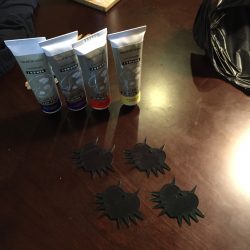
With the templates all complete, there was only one last step and arguably the most difficult: painting the design. I went to Blick and bought 4 different acrylic paints and some brushes.
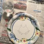
I traced the design onto a paper plate but the paint didn’t stick too well to it so I decided to set up some newspaper and paint a sample to that.
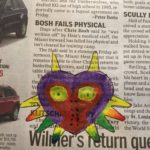
Happy with that, I taped down one of my acrylic’s with painters tape so I wouldn’t paint over any area’s I didn’t want to. I applied a base coat to the main part of the acrylic, waited for that to dry and painted many more layers.
The dark green of the acrylic made it so that if the purple was going to show up, there needed to be more than a few coats. After that, I taped out an area for me to paint the inner red design, then taped out an area for the eyes. Upon removing the tape however, I wasn’t too happy with the angular look of the center design so I decided to paint another acrylic following the same steps. Instead of taping out the center design this time, I did it by hand was much happier with the results. All that remained after that was painting the tiny stems of the design, which wasn’t too difficult. I applied coats in small doses and made sure to blend the areas that needed blending.
Looking back on this project, I think this is the happiest I’ve been with all of my projects. I think I had an epiphany after my last project: it’s all about simplicity. A week before school started I watched Jiro Dreams of Sushi and while I definitely enjoyed it, I was mystified by how a man could dedicate his entire life to something that was so simple. He essentially said that all he wanted to do was make the perfect piece of sushi and I thought to myself, “How hard could that be? Would it require a literal lifetime of dedication.” Now I understand. Yes. It would. In order to do something perfectly, to make a bowl or, furniture or what have, you need to dedicate so much of your time to it, regardless of how simple it may seem.
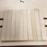
I wasn’t too happy after my flashlight. I was pleased with the amount of work that I put into it but as I sat in class listening to people share I felt ashamed. I was going to share my first real failure at ITP but I just felt too downtrodden to do it, too ready to move past it and learn from it. So in order to learn I had this crazy notion that I needed to go harder this week, do something more, something bigger and more creative. Originally I wanted to do shelves but then I thought a customizable pedal board would be cool.
When I did the flashlight, I learned the rule: “Be prepared for the unexpected”. My second project I learned that “be prepared for the unexpected” isn’t a rule, it’s a universal truth.
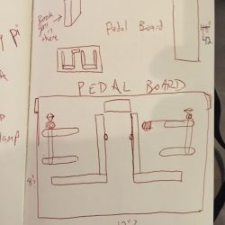
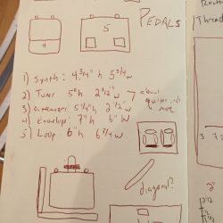
I got a head start immediately after class. I sketched a pedal board in my notebook and after a conversation with you, Ben, thought it would be cool to add a customizable feature. I figured I could use the router to make four ½” holes in the board and put nuts and a bolt in them to allow adjustability for the pedals. I went home that night and measured the five pedals I had to see how many inches my “holders” would need to be.
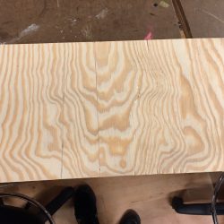
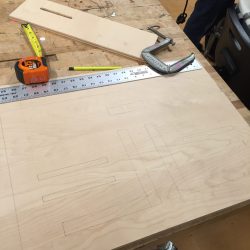
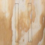
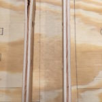
I was excited to get started so I looked around for some unused plywood. I luckily found a discarded piece of 24×14 1” ply and used it to draw my first prototype
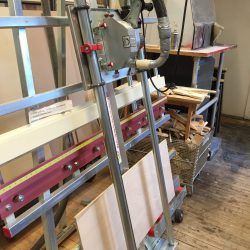
Then I took the wood and put it in the panel saw. I did this after measuring because I wanted to double check that after I put everything down in the prototype, all my pedals would fit. In hindsight I should’ve done more accurate measuring from the get-go but I got lucky in that the size ended up being close to right.
Once my measurements were more finalized, I went to Home Depot to pick up more wood. Unfortunately however, Home Depot was blocked off because of the explosion in Chelsea, so I headed to Lowe’s. It turned out they only had ½” ply which wasn’t ideal. I really wanted something a bit more firm because pedal boards can take a beating but because I didn’t know how long before Home Depot would re-open, I decided to buy 5 pieces of ply.
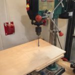
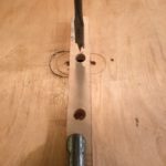
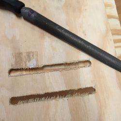
Knowing that I would need to use the router in order to make the holes for the customizable part, I signed up for office hours. After a great lesson – thanks again, Ben – I got started. First, I used my measurements in my diagram to trace where I need to route. Then I used the drill press to put holes in those measurements. This was to ensure that when I was routing, I would know where to start. After drilling those holes, I went over to the router and began routing my life away. I gave each hole a good four or fives passes with the router and I used a C clamp and a block as a customized stopper so I would know when I need to stop routing. I was so preoccupied with getting this right however that I only got a photo of the final product.
I am text block. Click edit button to change this text. Lorem ipsum dolor sit amet, consectetur adipiscing elit. Ut elit tellus, luctus nec ullamcorper mattis, pulvinar dapibus leo.
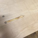
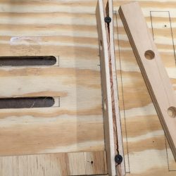
With the main holes routed, I had three more big steps: cut out the pieces of wood that would serve as sort of an L shaped or reverse L shaped stopper, drill holes in those pieces so that the wires from the pedal would have a place to go and drill holes in the top of the board so any excess wires could be run through the back.
After that is where I ran in to some very frustrating trouble. I thought I could just screw the thin panels that I’d cut into the wood. I bought some ¾’ inch screws and tried to screw the bottom of the L into the wood to no avail. I took a deep breath, tried again. No luck. I tried the vertical part of the L: it stripped the wood. Frustrated truly beyond belief, I asked you for help and you suggest I glue the smaller piece of panel – very wise and try using pilot holes for the vertical pieces of the wood.
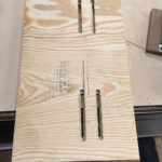
I tried doing that and had a lot more success.
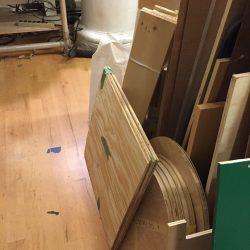
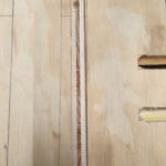
I had one more step now before spray painting: filing off excess wood.
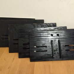
Now that I had clean wood, I applied the finishing touches and finally had a final product.
This exercise was another great lesson for me. I bit off a bit more than I could chew which probably wasn’t the best idea but I ended up getting very comfortable using the router, the band saw, the drill press, spray paint and more. I walked around Home Depot (I ended up going back on Tuesday to get spray paint and some bolts) like I actually knew what I was talking about and that felt good. I learned that things will very unexpectedly go wrong and that’s cool, we have a week. With that said, make your project manageable and if it’s a bit too big for your britches spend a LOT of time early on. Even more so than I did. Eager to apply these lessons to the next project.
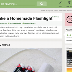
I have to admit I did not start this flashlight with an idea in mind and I regret that. Not because I think it was the wrong way to go about it or anything, but…well, I guess I’ll get to the reasoning in a bit. Having never really made anything before, I decided to cling to everyone’s favorite security blanket: Google. After a few minutes perusing the results for DIY flashlight, I found something that I felt capable of using as a resource.
DIY Flashlight
My plan was to make a sort of bare bones flashlight that I could customize. I figured I could take the cardboard and either paint it or put a design on it. After building the first model, I decided I wanted a bit more of a challenge and came up with the following idea.
My nephew lives up town and I figured I’d keep with the spirit of the project, and make something for him. I thought it would be a good idea to customize the flashlight to have different attachments that could fit onto the front. This is where the idiom “The best laid plans of mice and men” really applies.
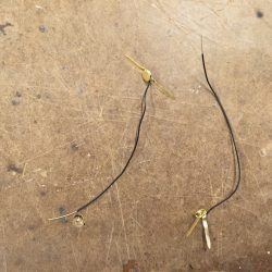
The first thing I did was attach my wire to my fasteners.
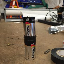
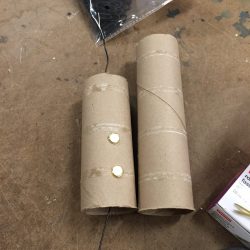
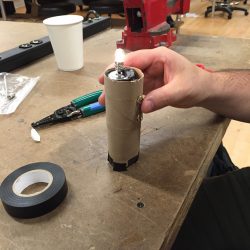
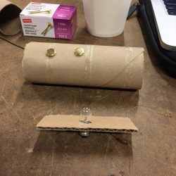
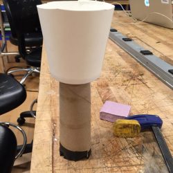
After that, I used my electricaltape to secure two D batteries together. This was, unfortunately, the straightest I was able to get them. I took my two fasteners and stuck them into a cardboard tube about 2.5” apart from one another. After having inserted the batteries, I wasn’t too happy with the size of the cardboard tube, so I used a larger one instead. I taped the wire attached to the lower fastener to the bottom of the electrical tape and left the top wire exposed out the top.
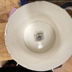
Just to make sure the light worked, I placed the wire from the top fastener around the bulb, put the bulb on the top of the D battery and used my “switch” – a paperclip I stripped with wire strippers – to connect the two fasteners. It worked, but here’s where problems arose. The wire wasn’t holding the bulb in place well enough. Especially not well enough for me to attach a cup on top. The bulb obviously needs to remain rested on top of the D battery for it to work but it wasn’t staying in place. At first, I tried to use cardboard to keep it place but to no avail.
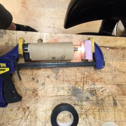
Then I tried to solder the wire to the bulb, which made things a little bit easier but not for long. While the bulb was definitely closer to the top of the D battery, it still wasn’t touching the D battery. It was missing it by about half a centimeter which was very frustrating.
After experimenting with electrical tape, I decided to ask some of the shop staff for questions. Emmanuel (I believe was his name, though I’m not sure on how to spell it) gave me some recommendations, but also gave me some fantastic advice that I think is going to stick with me: it’s often better to use rigid instruments when you’re making things because they’re set and won’t move around as much and can be sturdier. This was the problem I was running into exactly. I had malleable instruments – cardboard, paperclips, fasteners – thinking the easier they are to manipulate, the better it would be to customize and adapt. Instead, I got a flimsy, fragile product.
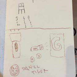
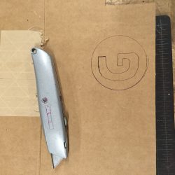
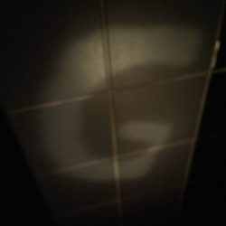
After an hour or so of looking for solutions and trying out suggestions from staff members – glue gun, more soldering, changing materials – the only thing that worked for a consistent amount of time was good old scotch tape so that’s what I used. Even this wasn’t ideal though because when I put the “head” of the flashlight on – the cut in half water cup – sometimes the light would flicker. To be honest, at this point, I thought to myself, “Fuck it. Maybe it’s ok to just have a working light without the decal that I want to attach to it,” (see sketch) but I didn’t want to give in. I used a box cutter to cut the “G” (to stand for “Gabi,” my nephew who I intended to give the flashlight to) out of cardboard and nestled it into the cup for a finished product.
I learned a LOT in the creation of this light bulb. Despite the fact that it worked, I really consider this my first failure of ITP. It didn’t live up to my design standards, is a bit too flimsy and is unimaginative. Would I change the experience then? No. I’m happy I learned what it feels like to fail, because I feel like I learned much more than had I succeeded.